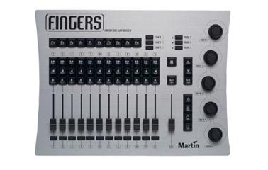
by Glenn Meader Sept. 12, 2005

Set serial port to 19200 baud 8 bits 1 stop bit
When you powerup Fingers, it transmits:
[Martin 'Fingers' V1.4 (C) 2003 Beiner van Beeck GbR]
It then transmits 6 character ASCII messages. Each message ends in CRLF (x0D x0A)
The first character indicates the kind of device (key, fader, datawheel)
X=fader
J=datawheel
K=pushbutton keydown
Q=pushbutton keyup
Fingers continuously puts out the levels for the 13 faders - about 1 per second:
X <fader number = 1 hex char (0-c)> <value=2 hex characters (00-ff)> CRLF
Fader 1 is number X0
Fader 2 is X1
Fader 3 is X2
GM is Xc
(each ends with a 2 character CRLF)
X000 = fader 1 at zero
Xa80 = fader 11 at 50%
X1d0 = fader 2 at about 75%
XcFF = GM fader at full
When you press a button, it sends a keydown code
and then a keyup code when you release the button
The code for keydown for the F1 key is K00.
The key up code is Q00. Each code ends with a CRLF.
F2 is K01 keydown, Q01 is F2 keyup
F10 is K09
>> 1 is K0a
>> 2 is K0b
>> 3 is K0c
>> 4 is K0d
>> 5 is K0e
>> 6 is K0f
>> 7 is K10
>> 8 is K11
>> 9 is K12
>> 10 is K13
>> 11 is K14
>> 12 is K15
< 1 is K16
< 2 is K17
< 12 is K21
> 1 is K22
> 2 is K23
> 12 is K2d
Square is K2e
B/O is K2f
Up arrow is K30
Down arrow is K31
R/S is K32
A is K33
B is K34
C is K35
D is K36
Shift 1 is K37
Shift 2 is K38
Shift 3 is K39
Mode 1 K3a
Mode 2 K3b
Mode 3 K3c
Bump 1 is K3d
Bump 2 is K3e
Bump 3 is K3f
Bump 4 is K40
Bump11 is K47
Bump 12 is K48
Data wheels are J0 thru J4
values are 01 for each few degrees of clockwise rotation
and ff for counterclockwise rotation
"J001" means datawheel 1 rotated a bit clockwise
"J3ff" means datawheel 4 rotated a bit counterclockwise
----------------------------------------------------------------------------
To Control the LEDs on Fingers, you transmit a 14 character ASCII message.
The first two characters of the message are: "L0" (zero)
The rest of the message is 3 groups of 4 Hex digits
there is no CRLF at the end of the message
| Group1 | Group2 | Group3 |
| XXXX | XXXX | XXXX |
| Mode and B/O | Chan 1-8 | ABCD and chan 9-12 |
Zero values command LEDs to be off.
if the first two characters in a group are the same as the second two characters,
the LEDs are on constantly.
The control of the LEDs is in binary so you can add hex digits to combine functions
(see examples below)
01 = nothing
02 = mode 1 red
04 = mode 1 green
08 = mode 2 red
10 = mode 2 green
20 - mode 3 red
40 = mode 3 green
80 = B/O green
01 = chan 1
02 = chan 2
04 = chan 3
08 = chan 4
10 = chan 5
20 = chan 6
40 = chan 7
80 = chan 8
01 = chan 9
02 = chan 10
03 = chan 11
04 = chan 12
10 = A key
20 = B key
40 = C key
80 = D key
L0000000000000 = all LEDs off
L0000000001010 = A key on constant
L0000000002020 = B key on constant
L0000000003030 = A and B keys on constant
L0000000001000 = Flash A key
L0000000000010 = Pulse A key
L0000000001020 = Flash A and pulse B
L0020200000000 = Mode 1 red
L0040400000000 = Mode 1 green
L0060600000000 = Mode 1 yellow
L0020400000000 = Mode 1 Green, pulsing yellow
L0040200000000 = Mode 1 red, pulsing yellow
L0121200000000 = Mode 3 green and Mode 1 red on constant
L00a0a00000000 = both Mode 1 and Mode 2 red constant
L00c0c00000000 = Mode 1 green and Mode 2 red constant
L0000001010000 = LED on Chan 1 >> key
L0000002020000 = LED on chan 2 >> key
L0000002000000 = flash LED on chan 2 >> key
L0000000020000 = pulse LED on Chan 2 >> key
L0000000000101 = LED on chan 9 >> key
L0000000000808 = LED 0n chan 12 >> key
L0000000000909 = LEDs 0n both chan 9 and chan 12 >> keys